


Plastic Rod End & Spherical Bearings for Versatile Applications
Lightweight | Self-Lubricating | Corrosion-Resistant
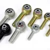
Our Plastic Rod End and Spherical Bearing Series
We know your customers demand lightweight, maintenance-free, and cost-effective motion solutions. That’s why we developed our plastic rod ends and spherical bearings, designed to perform in tough environments while reducing weight and eliminating lubrication needs.
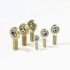
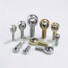
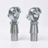
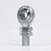
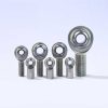
EFEM / KFEM
Plastic Spherical Bearings


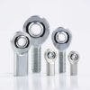
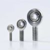
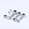
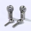
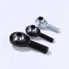
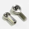
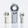
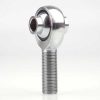
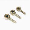
KORM / KOLM
Plastic Rod Ends
External Thread (Right / Left)


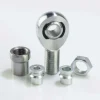
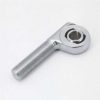
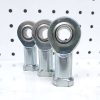
EIRM / EILM
Plastic Rod Ends
Internal Thread (Right / Left)


Plastic Rod End Bearing or Steel Rod End Bearing ?
| Category | Plastic Rod End Bearing | Steel Rod End Bearing |
|---|---|---|
| Advantages |
- Self-lubricating, no grease needed
- 50% lighter than steel - Vibration dampening - Resistant to dirt, dust, corrosion - Works in rotating, oscillating, and linear motions | - High static load capacity
- Better heat dissipation - High tightening torque - Smaller ID tolerance, precision-machined - With PTFE liner, also self-lubricating |
| Disadvantages | - Lower static capacity
- Larger tolerance E10 - Heat buildup - Lower tightening torque - Ball requires metal sleeve for fixing | - Heavier, up to 50% more
- Susceptible to corrosion unless stainless - Require lubrication, attracts dirt - Not vibration dampening |
Plastic Rod End and Spherical Bearing Size

| Part No. (Right-hand) | Part No. (Left-hand) | d | d2 | m | B1 | B2 | h1 | h2 | h3 | Maximum Swing Angle |
|---|---|---|---|---|---|---|---|---|---|---|
| KORM-05 | KOLM-05 | 5 | 19 | M05 | 4.4 | 6 | 36 | 20 | 45.5 | 33° |
| KORM-06 | KOLM-06 | 6 | 21 | M06 | 4.4 | 6 | 36 | 20 | 46.5 | 27° |
| KORM-08 | KOLM-08 | 8 | 24 | M08 | 6 | 8 | 41 | 24 | 53 | 24° |
| KORM-10 | KOLM-10 | 10 | 29 | M10 | 7 | 9 | 47.5 | 27 | 62 | 24° |
| KORM-10 F | KOLM-10 F | 10 | 29 | M10×1.25 | 7 | 9 | 47.5 | 27 | 62 | 24° |
| KORM-12 | KOLM-12 | 12 | 34 | M08 | 8 | 10 | 54 | 29 | 71 | 21° |
| KORM-12 F | KOLM-12 F | 12 | 34 | M12×1.25 | 8 | 10 | 54 | 29 | 71 | 21° |
| KORM-15 | KOLM-15 | 15 | 40 | M14 | 10 | 12 | 63 | 34 | 83 | 21° |
| KORM-17 | KOLM-17 | 17 | 46 | M16 | 11 | 14 | 69 | 37 | 92 | 18° |
| KORM-17 F | KOLM-17 F | 17 | 46 | M16×1.5 | 11 | 14 | 69 | 37 | 92 | 18° |
| KORM-20 | KOLM-20 | 20 | 53 | M20×1.5 | 13 | 16 | 80 | 43 | 106.5 | 16° |
| KORM-20 M20 | KOLM-20 M20 | 20 | 53 | M20×2.5 | 13 | 16 | 80 | 43 | 106.5 | 16° |
| KORM-25 | KOLM-25 | 25 | 64 | M24×2.0 | 17 | 20 | 97 | 53 | 129 | 16° |
| KORM-30 | KOLM-30 | 30 | 73 | M30×2.0 | 19 | 22 | 113 | 65 | 149.5 | 13° |

| Part No. (Right-hand) | Part No. (Left-hand) | d | d2 | m | d3 | d4 | B1 | B2 | h1 | h2 | h3 | B3 | Maximum Rotation Angle |
|---|---|---|---|---|---|---|---|---|---|---|---|---|---|
| EIRM-04 | EILM-04 | 4 | 15 | M04 | - | - | 3.5 | 5 | 22.5 | 9.5 | 30 | SW08 | 33° |
| EIRM-05 | EILM-05 | 5 | 19 | M05 | 9 | 11 | 4.4 | 6 | 30 | 12 | 39.5 | SW09 | 33° |
| EIRM-06 | EILM-06 | 6 | 21 | M06 | 11 | 13 | 4.4 | 6 | 30 | 12 | 40.5 | SW11 | 27° |
| EIRM-08 | EILM-08 | 8 | 24 | M08 | 13 | 16 | 6 | 8 | 36 | 14 | 48 | SW14 | 24° |
| EIRM-10 | EILM-10 | 10 | 29 | M10 | 15 | 19 | 7 | 9 | 43 | 18 | 57.5 | SW17 | 24° |
| EIRM-10 F | EILM-10 F | 10 | 29 | M10×1.25 | 15 | 19 | 7 | 9 | 43 | 18 | 57.5 | SW17 | 24° |
| EIRM-12 | EILM-12 | 12 | 34 | M12 | 18 | 22 | 8 | 10 | 50 | 20 | 67 | SW19 | 21° |
| EIRM-12 F | EILM-12 F | 12 | 34 | M12×1.25 | 18 | 22 | 8 | 10 | 50 | 20 | 67 | SW19 | 21° |
| EIRM-15 | EILM-15 | 15 | 40 | M14 | 21 | 26 | 10 | 12 | 61 | 27 | 81 | SW22 | 21° |
| EIRM-16 | EILM-16 | 17 | 46 | M16 | 24 | 30 | 11 | 14 | 67 | 27 | 90 | SW27 | 18° |
| EIRM-16 F | EILM-16 F | 16 | 43 | M16 | - | - | 10.5 | 13 | 64.5 | 26.5 | 86 | SW22 | 21° |
| EIRM-17 | EILM-17 | 16 | 43 | M16×1.5 | - | - | 10.5 | 13 | 64.5 | 26.5 | 86 | SW22 | 21° |
| EIRM-17 F | EILM-17 F | 17 | 46 | M16×1.5 | 24 | 30 | 11 | 14 | 67 | 27 | 90 | SW27 | 18° |
| EIRM-20 | EILM-20 | 20 | 53 | M20×1.5 | 27 | 34 | 13 | 16 | 77 | 31 | 103.5 | SW30 | 16° |
| EIRM-20 M20 | EILM-20 M20 | 20 | 53 | M20×2.5 | 27 | 34 | 13 | 16 | 77 | 31 | 103.5 | SW30 | 16° |
| EIRM-25 | EILM-25 | 25 | 64 | M24×2.0 | 34 | 41 | 17 | 20 | 94 | 38 | 126.5 | SW36 | 16° |
| EIRM-30 | EILM-30 | 30 | 73 | M30×2.0 | 41 | 48 | 19 | 22 | 110 | 47 | 146.5 | SW41 | 13° |

| PART NO. E10 | d | D | L1 | L2 | F | Maximum Swing Angle | Maximum Static Load After Installation Into The Base Radial [N]/Axial [N] | Maximum Ball Torque [Nm] | Weight [GRAMS] |
|---|---|---|---|---|---|---|---|---|---|
| EFEM-04 | 4 | 12 | 5 | 3 | 0.5 | 37° | 600/50 | 1 | 0.4 |
| EFEM-05 | 5 | 14 | 6 | 4 | 0.5 | 33° | 1000/130 | 2 | 0.8 |
| EFEM-06 | 6 | 14 | 6 | 4 | 0.5 | 27° | 1200/150 | 2.5 | 0.9 |
| EFEM-08 | 8 | 16 | 8 | 5 | 0.5 | 24° | 1800/175 | 7 | 1.2 |
| EFEM-10 | 10 | 19 | 9 | 6 | 0.5 | 24° | 2500/400 | 14 | 1.9 |
| EFEM-12 | 12 | 22 | 10 | 7 | 0.5 | 21° | 3800/650 | 25 | 2.8 |
| EFEM-15 | 15 | 26 | 12 | 9 | 0.5 | 21° | 5500/1000 | 30 | 6.9 |
| EFEM-16 | 16 | 28 | 13 | 9.5 | 0.5 | 21° | 6000/1150 | 32 | 9 |
| EFEM-17 | 17 | 30 | 14 | 10 | 1 | 21° | 6300/1200 | 35 | 10.6 |
| EFEM-20 | 20 | 35 | 16 | 12 | 1 | 18° | 9000/1400 | 40 | 16.3 |
| EFEM-25 | 25 | 42 | 20 | 16 | 1 | 16° | 14000/2900 | 55 | 29 |
| EFEM-30 | 30 | 47 | 22 | 18 | 1 | 13° | 17000/4000 | 70 | 37.4 |
| EFEM-40 | 40 | 62 | 28 | 22 | 1 | 15° | 22500/2500 | 80 | 57 |

| PART NO. E10 | d | D | L1 | L2 | F | Maximum Swing Angle | Maximum Static Load After Installation Into The Base Radial [N]/Axial [N] | Maximum Ball Torque [Nm] | Weight [GRAMS] |
|---|---|---|---|---|---|---|---|---|---|
| KFEM-02 | 2 | 8 | 4 | 3 | 0.8 | 32° | 300/60 | 1 | 0.1 |
| KFEM-03 | 3 | 10 | 6 | 4.5 | 0.8 | 32° | 550/200 | 2 | 0.5 |
| KFEM-05 | 5 | 13 | 8 | 6 | 0.8 | 30° | 1300/500 | 5 | 1 |
| KFEM-06 | 6 | 16 | 9 | 6.5 | 0.8 | 29° | 1800/650 | 10 | 1.6 |
| KFEM-08 | 8 | 19 | 12 | 9 | 0.8 | 25° | 2700/1200 | 12 | 2.9 |
| KFEM-10 | 10 | 22 | 14 | 10.5 | 0.8 | 25° | 4000/1400 | 20 | 4.4 |
| KFEM-12 | 12 | 26 | 16 | 12 | 0.8 | 25° | 5400/1500 | 30 | 7 |
| KFEM-14 | 14 | 28 | 19 | 13.5 | 0.8 | 23° | 6000/2500 | 35 | 9.1 |
| KFEM-16 | 16 | 32 | 21 | 15 | 0.8 | 23° | 8000/3000 | 40 | 12.8 |
| KFEM-18 | 18 | 35 | 23 | 16.5 | 0.8 | 23° | 9000/4000 | 45 | 16.6 |
| KFEM-20 | 20 | 40 | 25 | 18 | 0.8 | 23° | 10000/5000 | 55 | 24.4 |
| KFEM-22 | 22 | 42 | 28 | 20 | 0.8 | 22° | 11700/6500 | 60 | 28.5 |
| KFEM-25 | 25 | 47 | 31 | 22 | 0.8 | 22° | 13600/7500 | 65 | 39.3 |
| KFEM-30 | 30 | 55 | 37 | 25 | 1 | 22° | 20000/9000 | 70 | 62.6 |

| PART NO. E10 | d | D | L1 | L2 | F | Maximum Swing Angle | Maximum Static Load After Installation Into The Base Radial [N]/Axial [N] | Maximum Ball Torque [Nm] | Weight [GRAMS] |
|---|---|---|---|---|---|---|---|---|---|
| EFEM-15 LC | 15 | 26 | 12 | 9 | 0.5 | 30 | 5500/1000 | 21° | 4.5 |
| EFEM-16 LC | 16 | 28 | 13 | 9.5 | 0.5 | 32 | 6000/1150 | 21° | 6 |
| EFEM-20 LC | 20 | 35 | 16 | 12 | 1 | 40 | 9000/1400 | 18° | 11 |
| EFEM-25 LC | 25 | 42 | 20 | 16 | 1 | 55 | 14000/2900 | 16° | 20 |
| EFEM-30 LC | 30 | 47 | 22 | 18 | 1 | 70 | 17000/4000 | 13° | 26 |

| PART NO. E10 | d | D | L1 | L2 | F | Maximum Static Load After Installation Into The Base Radial [N]/Axial [N] | Maximum Ball Torque [Nm] | Weight [GRAMS] |
|---|---|---|---|---|---|---|---|---|
| KFEM-05LC | 5 | 13 | 8 | 6 | 0.8 | 1300/500 | 30° | 1 |
| KFEM-10LC | 10 | 22 | 14 | 10.5 | 0.8 | 4000/1400 | 25° | 4.3 |
| KFEM-12LC | 12 | 26 | 16 | 12 | 0.8 | 5400/1500 | 25° | 6.9 |
| KFEM-16LC | 16 | 32 | 21 | 15 | 0.8 | 8000/3000 | 23° | 12.7 |
| KFEM-18LC | 18 | 35 | 23 | 16.5 | 0.8 | 9000/4000 | 23° | 16.6 |
| KFEM-20LC | 20 | 40 | 25 | 18 | 0.8 | 10000/5000 | 23° | 23.6 |
| KFEM-25LC | 25 | 47 | 31 | 22 | 0.8 | 13600/7500 | 22° | 38.9 |
| KFEM-30LC | 30 | 55 | 37 | 25 | 1 | 20000/9000 | 22° | 61 |

| PART NO. E10 | d | D | L1 | F | Maximum Swing Angle | Maximum Static Load After Installation Into The Base Radial [N]/Axial [N] | Maximum Static Compressive Strength (Long-term) Radial [N]/Axial [N] | Weight GRAMS |
|---|---|---|---|---|---|---|---|---|
| KFEM-08 SL | 8 | 14 | 9 | 0.5 | 5° | 2700/450 | 1350/225 | 1.1 |
| KFEM-10 SL | 10 | 16 | 10.5 | 0.5 | 5° | 4000/750 | 2000/375 | 1.5 |
| KFEM-12 SL | 12 | 18 | 12 | 0.5 | 5° | 4500/750 | 2250/375 | 2 |
| KFEM-16 SL | 16 | 22 | 15 | 0.5 | 5° | 6500/500 | 3250/250 | 3.1 |
Customization Services
Materials
- Specially Formulated Engineering Plastics: High wear resistance, self-lubricating, maintenance-free.
- Reinforced Composites: For higher load-bearing applications.
- UV- and Chemical-Resistant Polymers: Ideal for outdoor, agricultural, and medical industries.
Customization Options
- Dimensions: Threads (M, UNF, UNC), bore sizes, and housing geometries can be fully tailored to your drawings.
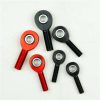
- Colors: Standard black and white, plus optional colors (red, blue, green, etc.) to match branding or identification needs.
- Logo Branding: Woven labels, laser marking, or customized embossing on housing for OEM/ODM projects.
- Packaging: From bulk poly bags to custom-designed color boxes, including logo, barcode, and instruction leaflets.
- Assemblies: Available as standalone rod ends / spherical bearings, or integrated into assemblies with shafts, flanges, or plastic nuts.


Need Help with Your Project?
Process Flow of Plastic Rod End and Spherical Bearings
- 1. Mold Drawing Design
- 2. Mold Fabrication
- 3. Mold Approval (After Confirmation)
- 4. Trial Molding
- 5. Material Drying
- 6. Mold Installation
- 7. Injection Machine Setup & Adjustment
- 8. Dimensional and Assembly Tolerance Inspection
- 9. Mass Production (After Successful Validation)

Engineered for Multi-Industry Application
Industrial Equipment
Textile machines, filling systems, packaging lines


Agricultural & Light Mobility
Agricultural machinery, bicycles, wheelchairs


Medical Applications
Medical devices, hospital beds, dental chair


Precision Systems
Weighing equipment, solar trackers, drones


Automotive & Transport
Cars, buses, high-speed trains


More Rod End Bearings
We offer a comprehensive range of rod end bearings to meet your specific application needs. Filter by application to find your solution.

Structure: Loader Slot Heavy Duty
Models: XM(Male Thread) / XF(Female Thread)
Material: 4130 Chromoly Steel
Bore: 0.1900~2.0000
Thread: 10-32~2-12 Inch
Static Load: 2,851~225,924 lbs

Structure: Loader Slot Offset
Models: XM-OS(Male Thread)
Material: 4130 Chromoly Steel
Bore: 0.7500~0.8750
Thread: 3/4-16,7/8-14 Inch

Structure: 3-Piece Offset
Models: JMX-OS(Male Thread)
Material: 4130 Chromoly Steel
Bore: 0.7500~0.8750
Thread: 7/8-14 Inch

Structure: Loader Slot Heavy Duty
Models: AM(Male Thread) / AF(Female Thread)
Material: Aluminum
Bore: 0.1900~1.0000
Thread: 10-32~1-14 Inch
Static Load: 788~36,285 lbs

Structure: Loader Slot Heavy Duty
Models: EXM(Male Thread) / EXF(Female Thread)
Material: Carbon Steel
Bore: 0.1900~1.0000
Thread: 10-32~1-12 Inch
Static Load: 1,169~43,541 lbs

Structure: 2-Piece Commercial Industrial
Models: CM-T(Male Thread) / CF-T(Female Thread)
Material: Carbon Steel
Bore: 0.1250~1.0000
Thread: 10-32~1 1/4-12 Inch
Static Load: 700~16,922 lbs

Structure: 2-Piece Commercial Industrial
Models: SCM-T(Male Thread) / SCF-T(Female Thread)
Material: Stainless Steel
Bore: 0.1900~1.0000
Thread: 10-32~1 1/4-12 Inch
Static Load: 1,190~11,595 lbs

Structure: 2-Piece Commercial Industrial
Models: PCM(-T)(Male Thread)
Material: 4130 Chromoly Steel
Bore: 0.3750~0.7500
Thread: 3/8-24~3/4-16 Inch
Static Load: 9,088~27,000 lbs

Structure: 2-Piece Commercial Industrial
Models: PCYM-T(Male Thread) / PCYF-T(Female Thread)
Material: 4130 Chromoly Steel
Bore: 0.3750~0.7500
Thread: 3/8-24~3/4-16 Inch
Static Load: 11,050~30,290 lbs

Structure: 3-Piece Precision
Models: JMX(-T)(Male Thread) / JFX(-T)(Female Thread)
Material: 4130 Chromoly Steel
Bore: 0.1900~1.2500
Thread: 10-32~1 1/4-12 Inch
Static Load: 2,851~138,800 lbs

Structure: 3-Piece Precision
Models: HJMX(-T)(Male Thread)
Material: 4130 Chromoly Steel
Bore: 0.3750~0.7500
Thread: 3/8-24~3/4-16 Inch
Static Load: 11,410~44,650 lbs

Structure: 3-Piece Precision
Models: ALJM(-T)/ALRSM(-T)(Male Thread) / ALJF(-T)(Female Thread)
Material: Aluminum
Bore: 0.1900~0.7500
Thread: 10-32~3/4-16 Inch
Static Load: 1,360~23,390 lbs

Structure: 3-Piece Precision
Models: JM(-T)(Male Thread) / JF(-T)(Female Thread)
Material: Carbon Steel
Bore: 0.1250~1.2500
Thread: 10-32~1 1/4-20 Inch
Static Load: 500~43,555 lbs

Structure: 3-Piece Precision
Models: VM(Male Thread) / VF(Female Thread)
Material: Carbon Steel
Bore: 0.1900~0.7500
Thread: 10-32~3/4-16 Inch
Static Load: 1,169~11,518 lbs

Structure: Injection Molded
Models: PM(Male Thread) / PF(Female Thread)
Material: Carbon Steel
Bore: 0.1900~0.7500
Thread: 10-32~3/4-16 Inch
Static Load: 1,174~10,937 lbs

Structure: Loader Slot Heavy Duty
Models: MXM(Male Thread) / MXF(Female Thread)
Material: 4130 Chromoly Steel
Bore: 5~50
Thread: M5*0.8~M48*2.0
Static Load: 7.8~195 kn

Structure: 2-Piece Commercial Industrial
Models: CM-M(Male Thread) / CF-M(Female Thread)
Material: Carbon Steel
Bore: 3~20
Thread: M3*0.5~M20*1.5
Static Load: 1,775~57,101 n

Structure: 2-Piece Commercial Industrial
Models: SCM-MT(Male Thread) / SCF-MT(Female Thread)
Material: Stainless Steel
Bore: 5~20
Thread: M5*0.8~M20*1.5
Static Load: 4,056~37,391 n

Structure: 3-Piece Precision
Models: JMX-M(Male Thread) / JFX-M(Female Thread)
Material: Chromoly Steel
Bore: 5~30
Thread: M5*0.8~M30*2.0
Static Load: 5,170~476,745 lbs

Structure: 3-Piece Precision
Models: JM-M(Male Thread) / JF-M(Female Thread)
Material: Carbon Steel
Bore: 5~30
Thread: M5*0.8~M30*2.0
Static Load: 5,170~193,732 lbs

Structure: 3-Piece Precision
Models: SA…TK(Male Thread) / SI…TK(Female Thread)
Material: Carbon Steel
Bore: 5~35
Thread: M5*0.8~M36*2.0
Static Load: 7.5~205.7 kn

Structure: Injection Molded
Models: MPM(Male Thread) / MPF(Female Thread)
Material: Carbon Steel
Bore: 5~20
Thread: M5*0.8~M20*1.5
Static Load: 5,000~36,000 n

Design: Studded
Material: 4130 Chromoly Steel / Carbon / Stainless Steel / Aluminum
Thread: Male / Female, LH / RH
Size: Inch / Metric

Design: Custom Rod End (Double Ends, Solid Rod Eye, Long Shank, High Misalignment,
Material: 4130 Chromoly Steel / Carbon / Stainless Steel / Aluminum
Size: Base on Your Drawing or Sample
| Material | Characteristics | Ultimate Tensile Strength | Best For | Best For | Recommended Rod Ends |
|---|---|---|---|---|---|
| Chromoly Steel | Superior strength, toughness, and significantly enhanced weldability. Performance is best after heat treatment. | 1040-1670 MPa (Heat Treated) | High-load, high-impact and heavy-duty applications like motorsports suspension and agricultural linkages. |   | Inch Models XM/XF, JMX/JFX Metric Models MXM/MXF, JMX-M/JFX-M |
| Carbon Steel | General-purpose and cost-effective, suitable for most standard industrial applications. | 620-680 MPa | Standard-duty industrial linkages and control mechanisms. |   | Inch Models CM/CF, VM/VF Metric Models CM-M/CF-M, SA...TK/SI...TK |
| Stainless Steel | Excellent corrosion resistance, hygienic, withstands chemicals and saltwater. | ~515-620 MPa | Marine vessels, food processing, chemical equipment, underwater, and agricultural machinery. |   | Inch Models SCM/SCF, XM-SS/XF-SS Metric Models SCM-M/SCF-M, MXM-SS/MXF-SS |
| Aluminum | 7075-T6 Aerospace Aluminum: Ultimate strength-to-weight ratio, weighing only one-third of steel | ~572 MPa | Weight-critical applications such as racing, weight reduction designs, and aerospace components. |   | Inch Models AM/AF,ALJM/ALJF Metric Models CUSTOM |
| Titanium | Ultimate strength-to-weight ratio, unmatched corrosion resistance, and high-temperature stability. | >1000 MPa (Heat Treated) | Aerospace, military, and top-tier motorsports where cost is secondary to performance. |  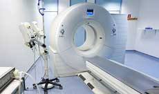 | Inch Models XM/XF,JMX/JFX Metric Models MXM/MXF,JMX-M/JFX-M |
Need Help with Your Project?
About SYZ ROD ENDS
Engineering & Design Support
Your Partner in Innovation
Accelerate your product development with our complete engineering resources. From concept to validation, we provide the technical data and files you need to integrate seamlessly and design with confidence.
Comprehensive PDF Datasheets / 3D STEP Files for instant CAD integration / 2D CAD Drawings (DWG, DXF) for precision detailing
OEM / ODM Customization
From Concept to Global Delivery
Requirement Analysis-Define application, performance metrics, and target cost
Engineering Design & 3D Modeling- Transform ideas into CAD drawings and 3D models
Prototyping & Validation-Rapid prototyping and testing for design accuracy
Tooling & Mass Production-From approved samples to large-scale manufacturing
Quality Assurance-Rigorous inspections for consistent performance
Packaging & Services
Beyond Products, We Deliver Value
We ensure your products arrive safe, secure, and ready for market. From professional standard packaging to fully customized solutions, our services are designed to support your brand on a global scale.
White-label box packaging for a clean, brand-ready look / Multi-language manuals for global users / Tailored solutions with reliable worldwide logistics support