

Studded rod end configuration
SYZ can quote the base rod-end series with the studded configuration. Send the rod-end bore, base series, stud thread, exposed length, material and quantity.
Request a Studded Configuration →Search by part number, series, material, application, or specification.
Press Enter to view all results Esc to close
Studded Mounting Configuration for Rod Ends & Heim Joints
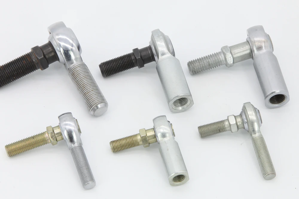
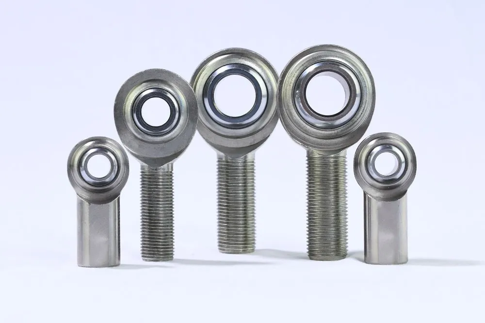
A rod end stud is a stepped shaft captured in a rod end’s spherical ball bore, replacing a through-bolt with a single-sided mounting thread. SYZ covers 8 bore-matched sizes from 3/16″ to 3/4″, UNF-2A 10-32 to 3/4-16, with carbon, alloy or stainless steel, SL left-hand and SX heat-treated alloy options.
Overview
Product Offerings
The stud is sized to the rod end’s spherical ball bore. Add S to the base rod-end part number for the studded configuration; use SL for a left-hand stud thread and SX for a heat-treated alloy stud. All threads below are external UNF-2A.
| Rod end bore | L ±.015″ | N ±.010″ | M ref. | Stud thread | Details |
|---|---|---|---|---|---|
| 3/16″ | 1.016″ | 0.500″ | 0.437″ | 10-32 | View size → |
| 1/4″ | 1.031″ | 0.562″ | 0.500″ | 1/4-28 | View size → |
| 5/16″ | 1.219″ | 0.687″ | 0.593″ | 5/16-24 | View size → |
| 3/8″ | 1.562″ | 0.906″ | 0.812″ | 3/8-24 | View size → |
| 7/16″ | 1.750″ | 1.062″ | 0.937″ | 7/16-20 | View size → |
| 1/2″ | 2.000″ | 1.125″ | 1.000″ | 1/2-20 | View size → |
| 5/8″ | 2.500″ | 1.500″ | 1.375″ | 5/8-18 | View size → |
| 3/4″ | 3.000″ | 1.812″ | 1.625″ | 3/4-16 | View size → |
Dimensional source: SYZ Rod End Stud specification. L and N are nominal dimensions with the published tolerances; M is a reference dimension. Confirm the base rod-end series and final drawing before production.
Engineering Guide
Industrial Uses
Studded rod ends simplify one-sided installation where a through-bolt is difficult to access, too large for the package or not compatible with a tapped boss.
Technical Guide
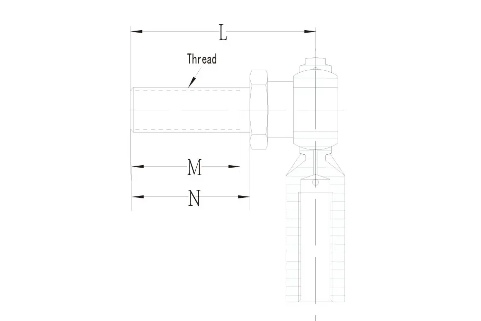
A standard rod end uses a through-bolt through the spherical ball bore. The studded configuration replaces that bolt with a stepped shaft captured in the ball, leaving an external UNF-2A thread for a tapped bracket, boss or arm.
For a quick engagement check, use the thread engagement depth calculator. The complete stud dimensions and tolerances remain on the rod end stud specification page.
Engineering Detail
Most stud failures start at the interfaces: too little thread engagement, an unseated shoulder, over-travel beyond the approximate ±25° envelope or a material choice that does not match the environment. Use the table as a design review prompt, not as a substitute for the applicable drawing and load calculation.
| Symptom | Cause | Prevention |
|---|---|---|
| Threads strip under load | Insufficient engagement | Engage ≥ ~1× thread diameter; don’t run the rod end near the end of the stud |
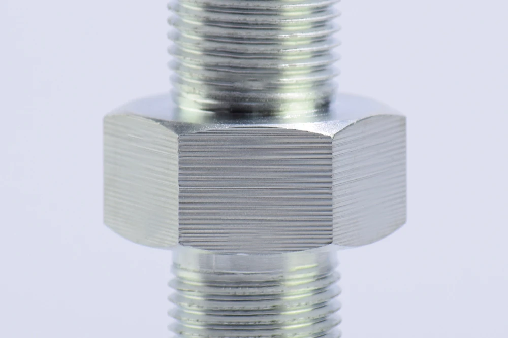
| Stud backs out in service | No jam nut / vibration | Jam-nut the joint and re-check after first run-in |
| Galling on install (stainless) | Stainless-on-stainless dry threads | Use anti-seize on stainless studs |
| Corroded/seized joint | Wrong material for environment | Specify the stainless option for moisture/salt/washdown |
Configuration & Sourcing
Complete the Link
FAQ
Engineering Tools
Factory Direct
Tell us your specific part numbers and quantities. We respond within 24 hours with pricing and lead time.