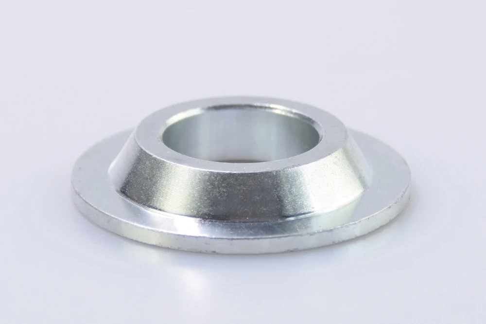
SG / HMS Series
High-MisalignmentTapered sleeves that seat inside the ball bore, reducing the bolt diameter while extending the neck outward. Essential for off-road link travel — 44° to 66° of misalignment depending on size.
Performance Spacers & Reducers for Automotive and Industrial Use
A rod end spacer locates the joint in its mount, adapts the bore to your bolt, and — in high-misalignment form — extends how far the joint can travel before it binds. SYZ machines three families: high-misalignment spacers (SG stainless / HMS carbon steel), cone spacers (SCNS/CNS) and mounting spacers (SCW/CW). 36 standard configurations, stainless or zinc-plated carbon steel, plus custom materials and finishes to drawing.

Mounting Hardware
Small part, big impact in every assembly. Spacers — also called reducers or standoffs — are precision-machined components that set alignment, spacing and isolation between parts. They keep positioning accurate, distribute load evenly across the mount, and stop metal-to-metal contact where it would do damage.
On a rod end specifically, the spacer sits between the spherical ball bore and your mounting brackets, and does two jobs: it locates and centres the bearing inside the bracket so it runs straight, and in high-misalignment form it increases the tilt angle before the rod housing binds against the tabs. On a suspension link that is actively cycling, the second job is the one that keeps parts from breaking.

What They Actually Do
Beyond alignment and spacing, spacers do several distinct technical jobs across mechanical systems — and knowing which one you need is what decides the family.

Product Selection
Three distinct designs, each offered in stainless steel for corrosion resistance and zinc-plated carbon steel for cost. Full size charts below each card.

Tapered sleeves that seat inside the ball bore, reducing the bolt diameter while extending the neck outward. Essential for off-road link travel — 44° to 66° of misalignment depending on size.

Cone-shaped locating spacers that centre the rod end body inside the brackets while keeping solid support faces. Cone angles from 16° to 28° by size.

Shouldered mounting spacers for general setups — centring the rod end, controlling installed width, or filling the gap inside a bracket. The widest size range of the three.
| Part No. (Stainless) | Part No. (Carbon) | D +.000 −.001 | D2 ±.005 | B +.003 −.000 | W ±.005 | W2 ±.005 | Mis. Angle | Total Installed Width |
|---|---|---|---|---|---|---|---|---|
| SG10-84 | HMS10-84 | 0.624 | 0.825 | 0.500 | 0.250 | 0.360 | 54 | 1.250 |
| SG10-813 | HMS10-813 | 0.624 | 0.875 | 0.500 | 0.837 | 0.363 | 44 | 2.425 |
| SG12-84 | HMS12-84 | 0.749 | 0.850 | 0.500 | 0.250 | 0.423 | 56 | 1.375 |
| SG12-88 | HMS12-88 | 0.749 | 0.850 | 0.500 | 0.500 | 0.423 | 58 | 1.875 |
| SG12-108 | HMS12-108 | 0.749 | 0.950 | 0.625 | 0.500 | 0.423 | 52 | 1.875 |
| SG12-812 | HMS12-812 | 0.749 | 0.950 | 0.500 | 0.775 | 0.423 | 54 | 2.425 |
| SG12-816W | HMS12-816W | 0.749 | 0.875 | 0.500 | 1.000 | 0.423 | 54 | 2.875 |
| SG14-813 | HMS14-813 | 0.874 | 1.000 | 0.500 | 0.813 | 0.423 | 52 | 2.500 |
| SG14-1010 | HMS14-1010 | 0.874 | 1.062 | 0.625 | 0.625 | 0.423 | 44 | 2.125 |
| SG14-1012 | HMS14-1012 | 0.874 | 1.000 | 0.625 | 0.775 | 0.423 | 46 | 2.425 |
| SG16-910 | HMS16-910 | 0.999 | 1.250 | 0.563 | 0.625 | 0.673 | 66 | 2.625 |
| SG16-1010 | HMS16-1010 | 0.999 | 1.250 | 0.625 | 0.625 | 0.673 | 64 | 2.625 |
| SG16-1012 | HMS16-1012 | 0.999 | 1.250 | 0.625 | 0.750 | 0.673 | 60 | 2.875 |
| SG16-1013 | HMS16-1013 | 0.999 | 1.250 | 0.750 | 0.813 | 0.673 | 60 | 3.000 |
| SG16-1210 | HMS16-1210 | 0.999 | 1.250 | 0.750 | 0.625 | 0.673 | 60 | 2.625 |
| SG16-1212 | HMS16-1212 | 0.999 | 1.250 | 0.750 | 0.750 | 0.673 | 57 | 2.875 |
HMS = zinc-plated carbon steel; SG = stainless steel (optional). D is the diameter that seats in the rod end ball bore, B is the bolt bore, and Total Installed Width is the reference stack the pair occupies between your tabs — check that figure against your bracket gap before ordering.
| Stainless Steel | Carbon Steel | A +.000 −.001 | B ±.005 | C +.003 −.000 | D ±.005 | E ±.005 | Q Angle |
|---|---|---|---|---|---|---|---|
| SCNS5 | CNS5 | 0.412 | 5/16 | 0.083 | 0.625 | 0.312 | 22° |
| SCNS6 | CNS6 | 0.500 | 3/8 | 0.083 | 0.750 | 0.312 | 25° |
| SCNS7 | CNS7 | 0.562 | 7/16 | 0.100 | 0.750 | 0.375 | 16° |
| SCNS8 | CNS8 | 0.592 | 1/2 | 0.100 | 0.875 | 0.375 | 28° |
| SCNS10 | CNS10 | 0.750 | 5/8 | 0.100 | 1.000 | 0.375 | 28° |
| SCNS12 | CNS12 | 0.894 | 3/4 | 0.125 | 1.375 | 0.437 | 18° |
SCNS = stainless steel; CNS = zinc-plated carbon steel. Cone spacers for rod ends and spherical bearings; standard (non-cone) spacers also available. B is the bolt size.
| Stainless Steel | Carbon Steel | Nominal Size +.000 −.001 | A ±.005 | B +.003 −.000 | C ±.005 | D ±.005 |
|---|---|---|---|---|---|---|
| SCW-8-2 | CW-8-2 | 1/2 | 0.870 | 0.510 | 0.684 | 0.230 |
| SCW-6-1 | CW-6-1 | 3/8 | 0.651 | 0.376 | 0.515 | 0.186 |
| SCW-4 | CW-4 | 1/4 | 0.700 | 0.251 | 0.331 | 0.142 |
| SCW-5 | CW-5 | 5/16 | 0.828 | 0.313 | 0.445 | 0.168 |
| SCW-6 | CW-6 | 3/8 | 0.930 | 0.376 | 0.515 | 0.184 |
| SCW-7 | CW-7 | 7/16 | 1.050 | 0.438 | 0.586 | 0.220 |
| SCW-10 | CW-10 | 5/8 | 1.420 | 0.626 | 0.839 | 0.270 |
| SCW-12 | CW-12 | 3/4 | 1.630 | 0.751 | 0.978 | 0.300 |
| SCW-8-1 | CW-8-1 | 1/2 | 0.750 | 0.510 | 0.684 | 0.230 |
| SCW-14 | CW-14 | 7/8 | 1.875 | 0.876 | 1.033 | 0.3125 |
| SCW-10-1 | CW-10-1 | 5/8 | 0.994 | 0.626 | 0.839 | 0.272 |
| SCW-12-1 | CW-12-1 | 3/4 | 1.141 | 0.751 | 0.978 | 0.302 |
| SCW-16 | CW-16 | 1.00 | 2.250 | 1.001 | 1.273 | 0.375 |
| SCW-8 | CW-8 | 1/2 | 1.240 | 0.501 | 0.684 | 0.228 |
SCW = stainless steel; CW = zinc-plated carbon steel. Note that several nominal sizes appear more than once with different shoulder profiles — 1/2″ is offered as SCW-8, SCW-8-1 and SCW-8-2 — so match on the A and C dimensions, not on nominal size alone.
Engineering Detail
A standard rod end pivots until the housing contacts the mounting tabs — and that contact point, not the bearing, is usually what limits your travel. SG/HMS spacers get around it by inserting a tapered neck directly into the ball bore, pushing the bolt contact face further outward so the housing can swing considerably further before it touches anything.
The angle you gain is in the size chart: 44° to 66° across the SG/HMS range, which is a real number you can check your suspension geometry against rather than a vague “high misalignment” claim.
For maximum articulation on severe off-road setups, pair these with a high-misalignment ball (HMBL), or step up to a purpose-built high-misalignment rod end series such as HJMX, PCM or PCYM.
High-misalignment spacers are used in pairs — one each side of the rod end ball. Three things have to line up:
1. Bolt size must match the spacer’s inner bore (column B). 2. Stack width — spacer + rod end ball + spacer — must match your mounting bracket opening; use the Total Installed Width column. 3. Resulting angle must stay within what the rod end itself allows, since a spacer cannot give the joint more travel than the housing permits.
| Series | Materials | Bolt / Bore Range | Angle |
|---|---|---|---|
| SG / HMS | Stainless / carbon steel | 0.500″ – 0.750″ bolt bore | 44° – 66° |
| SCNS / CNS | Stainless / carbon steel | 5/16″ – 3/4″ | 16° – 28° cone |
| SCW / CW | Stainless / carbon steel | 1/4″ – 1″ nominal | Straight (n/a) |
SG/HMS also seats a 0.624″ – 0.999″ diameter (column D) into the ball bore — match that to the rod end you are fitting, not just the bolt.
Materials
The three standard series ship in stainless or zinc-plated carbon steel. Beyond that, spacers are a machined part — so the material and finish are open to whatever the application needs.
| Material | Why You’d Pick It |
|---|---|
| 45# Carbon Steel | High strength and cost-effective — the standard CNS / CW / HMS material, zinc plated |
| 4130 / 4140 / 4340 | Enhanced fatigue resistance for cyclic, high-shock links |
| SS304 / 316 / 17-4 PH | Corrosion resistance for marine, washdown and outdoor service — the SG / SCNS / SCW material |
| 6061 / 7075 Aluminum | Light weight where unsprung or rotating mass matters |
| Others | Brass, nylon, engineering plastic, titanium — quoted per project |
| Surface Treatment | Feature |
|---|---|
| Zinc Plating | Anti-rust, cost-effective — the standard finish on carbon steel spacers |
| Black Oxide | Aesthetic finish with rust protection |
| Powder Coating | Enhanced durability, UV resistant |
| E-Coating | Uniform finish, environmentally friendly process |
| Anodizing | For aluminum — various colour choices |
Zinc-nickel and other specialised coatings are available on request where the corrosion spec calls for it.
Applications
Keeping linkages bind-free across steering, suspension and machinery mounts.
Required on crawlers and pre-runners so trailing arms and panhard links can cycle through their full travel arc without the housing binding on the tabs.
Centres tie-rod assemblies inside their mounting brackets and eliminates steering bind under fast rack movement.
Sets precise mounting gaps and preload for actuator links inside brackets, keeping movement lines clean and straight.
Where a spherical bearing package needs a controlled installed width, a compact cone spacer profile does it without adding stack height.
SG, SCNS and SCW stainless versions for washdown, marine and outdoor service where a plated carbon spacer would not last.
Supports fabricated chassis and linkage assemblies where stack-up and shoulder size decide whether the package fits at all.
Our Strengths


Beyond the Part
From concept to container, the technical and commercial support that lets a spacer drop straight into your product.
Accelerate development with the technical data you need to integrate and validate with confidence.
From concept to global delivery, in five stages.
Products that arrive safe, secure and ready for your market.
About SYZ Rod Ends
We specialise in durable, high-performance custom metal components for demanding industrial and automotive applications. Our own facility in Ningbo, together with two closely-affiliated production bases in Jiangsu, runs advanced CNC machining centres, heat-treatment lines and automated inspection systems, so every part meets strict performance, reliability and safety standards under ISO 9001:2015 certification (Cert. No. 11425Q49262R0S).
Trusted By

FAQ
Factory Direct
Specify your series (SG/HMS, SCNS/CNS or SCW/CW), material, bore, stack dimensions and quantities — or just send a drawing.