
Bracket & Mounting Buyers’ Guide
Brackets are fabricated support and attachment components that establish mounting points for rod ends, shocks, cylinders and custom linkages. This guide covers bracket geometry, materials and the selection criteria for chassis and machine applications.
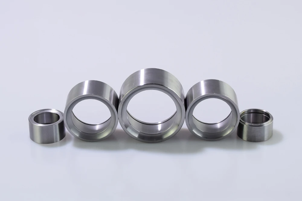
What Are Bracket & Mounting Components?
DefinitionBrackets and mounting components establish the mounting points that connect rod ends, shocks, cylinders, spherical joints and custom linkages to the surrounding chassis or machine structure. The bracket geometry determines alignment, load transfer, fastener access and weld or bolt support.
Select thickness, hole position, mounting width, material, surface treatment and fatigue resistance for the actual application. For weld-in uniball housings, see uniball cups.
- Also called
- Mounting brackets · tabs · weld plates
- Core function
- Structural mounting points for joints
- Mounting
- Weld-in or bolt-on
- Key dimensions
- Thickness · hole position · width
Bracket Geometry and Selection
StructureBracket selection is about matching the structural demand to the mount—four criteria drive the choice.
Thickness
Material thickness sets the bracket’s load capacity and weld mass—thicker for structural pivots, thinner for accessory mounts. Structural pivots typically 3/16″–3/8″ in A36 or 4130.
Hole Position & Diameter
Hole placement determines the joint’s geometry and the fastener size. Match to the rod-end bore or shock eyelet—common hole diameters 3/8″ to 5/8″.
Material
Carbon steel for weldability, chromoly for strength—finish after welding for corrosion protection.
Width & Alignment
Mounting width centers the joint; alignment through the bracket prevents side-loading the bearing or bushing. Typical uniball cup body OD range: 1.000″ to 2.750″.
Weld-In Brackets
Brackets welded directly into the chassis or arm—the strongest and most compact mounting method for structural pivots.
Requires weld access and post-weld finishing; the joint is permanent.
Bolt-On Brackets
Brackets bolted to the structure—removable and adjustable, useful for test fixtures, alignment setups and modular assemblies.
Trade-off: bolt holes weaken the bracket compared to a continuous weld.
What a Bracket Does in the Structure
FunctionFour engineering jobs—each maps to a bracket design decision.
Transfer load to the structure
The bracket is the load-path bridge between the joint and the chassis—thickness and material must carry the working and shock loads.
Locate the joint
Hole position and bracket geometry define the joint’s working angle and alignment—precision here prevents side-loading.
Support weld or bolt
The bracket’s weld edge or bolt pattern must suit the fabrication method—weld-in for structural pivots, bolt-on for serviceable mounts.
Resist fatigue
Cyclic loading on suspension and machine pivots fatigues thin or poorly supported brackets—size for the duty cycle.
Where brackets fail in the field
- Under-thickness for the load—size the plate to the working and shock load with a fatigue margin; structural pivots typically 3/16″–3/8″ in A36 or 4130.
- Poor hole alignment, side-loading the bearing or shock.
- Insufficient weld penetration—specify the weld size and process for the load path, not the minimum that holds the bracket in place.
- Ignoring fatigue cycles on suspension-duty brackets.
Bracket Materials and Finishes
MaterialsMaterials are chosen for weldability and strength; finishes are applied after fabrication.
Carbon Steel
Weldable standardThe default material—welds cleanly to chassis and arm structures, economical and strong.
4130 Chromoly
High-strength optionFor high-load pivots where the bracket is a structural member in a performance suspension.
Materials and Finishes
Surface treatmentSurface finishing happens at fabrication—the bracket is supplied bare.
| Treatment | Applied to | Series examples | What it does |
|---|---|---|---|
| Carbon steel, bare | Supplied condition | All brackets | Ready to weld; finish after. |
| Post-weld finishing | Fabrication level | Completed brackets | Paint, powder coat or plating after welding. |
Material notes: always finish welded brackets to protect the weld and surrounding metal from corrosion.
Where Brackets Perform
ApplicationsAnywhere a joint needs a structural mount.
Rod-End & Shock Mounting
Mounting brackets provide secure attachment for spherical rod ends and shock absorbers.
Weld-inChromolyCylinder Mounts
Pneumatic and hydraulic cylinder pivots welded into machine frames.
Carbon steelCustom Linkage Fabrication
Custom tabs and brackets for one-off and production linkage assemblies.
CustomHow to Choose: 4 Steps
Selection referenceDefine the Joint
Rod end, shock, cylinder or custom pivot—the joint type sets the hole and width.
Size for Load
Thickness and material carry the working and shock loads—accessory mounts commonly 1/8″–3/16″; structural suspension pivots 3/16″–3/8″ in A36 or 4130.
Choose Mounting
Weld-in for structural pivots; bolt-on where service access or adjustability matters.
Plan the Finish
Bare for welding; paint or coat after fabrication to protect the weld zone.
| Attribute | Specification | Notes | Where |
|---|---|---|---|
| SYZ bracket & mounting | |||
| Mounting type | Weld-in · bolt-on | By structural demand | View |
| Material options | Carbon steel · 4130 chromoly | Chromoly for performance | View |
| Custom brackets | To drawing | Production & one-offs | View |
Mounting a spherical bearing? See uniball cups for weld-in bearing housings. For threaded rod-end pivots, see the rod end range.
Get Selection HelpBracket Buyers’ Questions
FAQQ1Weld-in or bolt-on—which should I use?
Q2What thickness do I need?
Q3Can I get custom bracket geometry?
Q4What material for off-road brackets?
Related component families? See rod eyes, clevis rod ends and weld-in tube adapters for the mating hardware around a bracketed joint.
Selecting Brackets & Mounting Components?
Send us the joint type, load and mounting dimensions—SYZ engineers reply with the right bracket and factory-direct pricing.